商品概要
画像をクリックすると大きくなります
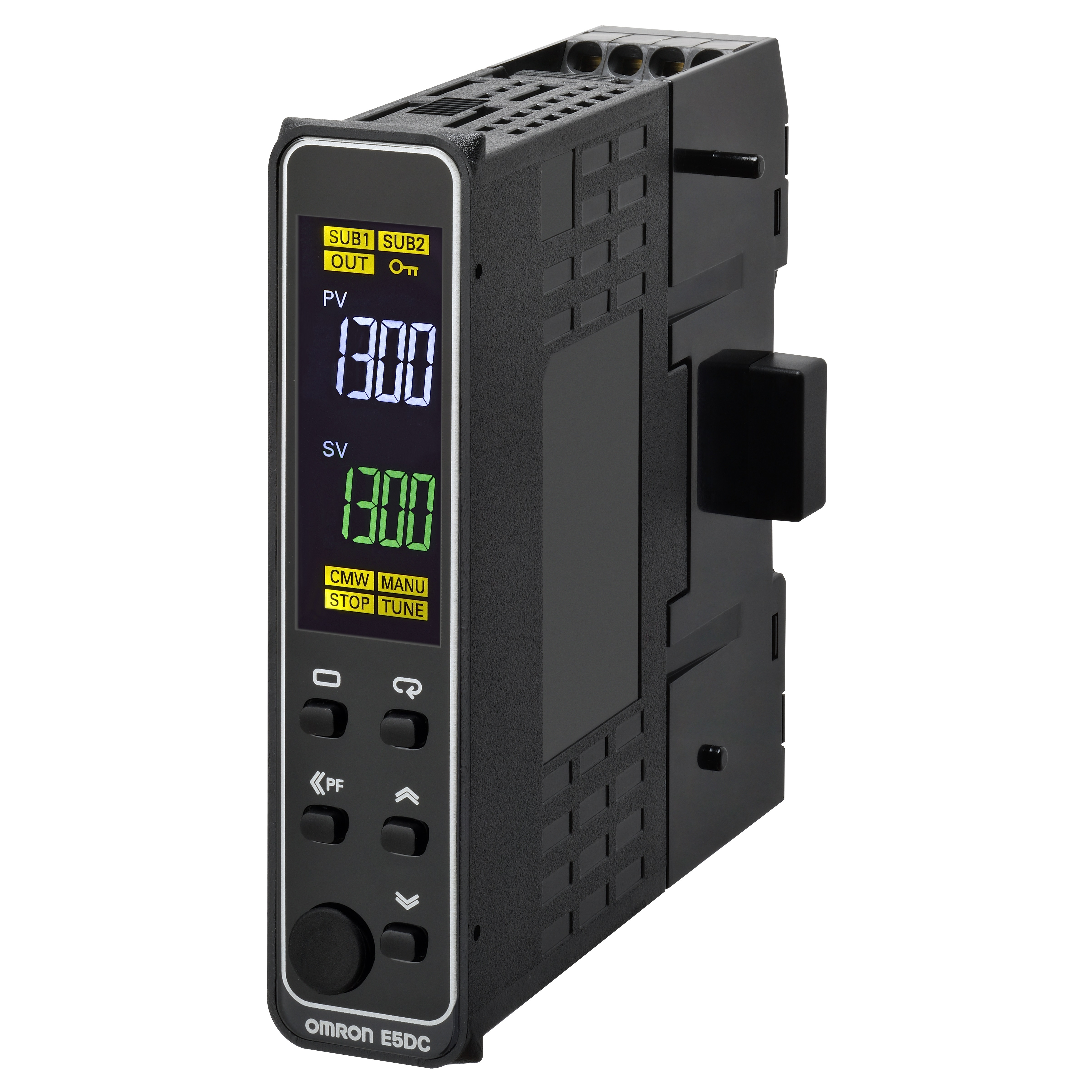
Digital Temperature Controller, 22.5 mm wide, Relay output, Auxiliary output: 2, Power supply voltage: 100 to 240 VAC, Push-In Plus terminal block model, Universal inputs
在庫/販売状況
2026/03/30 00:00 情報更新| 販売状況 | 販売中 |
|---|---|
| 機種区分 | 標準在庫機種 |
| 在庫状況 | 〇 |
| 標準価格(税別) | ¥ 25,500 |
詳細情報
定格/性能
情報更新:2025/10/23
| Shape | 22.5 mm wide |
|---|---|
| Fixed/Programmable | Fixed |
| Rated frequency | 50/60 Hz |
| Operating voltage range | 85 to 110% of the power supply voltage |
| Power consumption | W | 1.5 W max.(at 24 VDC) |
| Power consumption | VA | 2.8 VA max.(at 24 VAC) |
| Number of input points | 1 point |
| Temperature input | 10 to 70 ℃, 60 to 120 ℃, 115 to 165 ℃, 140 to 260 ℃(Infrared Thermosensor (ES1B)) K, J, T, E, L, U, N, R, S, B, C/W, PLII(Thermocouple) Pt100, JPt100(Platinum resistance thermometer) |
| Analog input | 1 to 5 V, 0 to 5 V, or 0 to 10 V(Voltage input) 4 to 20 mA or 0 to 20 mA(Current input) |
| Input impedance | Current input: 150 Ω max., voltage input: 1 MΩ min. (Applicable when connecting 1:1 to ES2-HB-N/THB-N.) |
| Control method | ON/OFF control or 2-PID control (with auto-tuning) |
| Number of total control output | 1 point |
| Control output 1 | Relay output |
| Control output 2 | None |
| Output | SPST-NO, 250 VAC, 3 A (resistive load) |
| Points | 1 point |
| Minimum applied load (Reference value) | 10 mA at 5 V (reference value) |
| Number of total auxiliary output | 2 point |
| Output specifications | SPST-NO relay outputs: 250 VAC, 2 A (resistive load), Electrical life: 100,000 operations, Minimum applicable load: 10 mA at 5 V (reference value) |
| Setting method | Digital setting using front panel keys (with protection function) |
| Indication method | 11-segment digital display and individual indicators 2-step display Character height PV: 8.5 mm/ SV: 8 mm |
| Multi SP functions | Up to eight set points (SP0 to SP7) can be saved and selected using key operations. |
| BANK switch functions | None |
| Input sampling peirod | 50 ms |
| Hysteresis | Temperature input: 0.1 to 999.9 ℃ or °F (in units of 0.1 ℃ or °F) Analog input: 0.01 to 99.99% FS (in units of 0.01% FS) |
| Proportional band | Temperature input: 0.1 to 999.9 ℃ or °F (in units of 0.1 ℃ or °F) Analog input: 0.1 to 999.9% FS (in units of 0.1% FS) |
| Integral time | 0 to 9999 s (in units of 1 s), 0.0 to 999.9 s (in units of 0.1 s) |
| Derivative time | 0 to 9999 s (in units of 1 s), 0.0 to 999.9 s (in units of 0.1 s) |
| Proportional band (P) for cooling | Temperature input: 0.1 to 999.9 ℃ or °F (in units of 0.1 ℃ or °F) Analog input: 0.1 to 999.9% FS (in units of 0.1% FS) |
| Integral time (I) for cooling | 0 to 9999 s (in units of 1 s), 0.0 to 999.9 s (in units of 0.1 s) |
| Derivative time (D) for cooling | 0 to 9999 s (in units of 1 s), 0.0 to 999.9 s (in units of 0.1 s) |
| Control period | 0.1 s, 0.2 s, 0.5 s, 1 to 99 s (in units of 1 s) |
| Manual reset value | 0.0% to 100.0% (in units of 0.1%) |
| Insulation resistance | 20 MΩ min. (500 VDC)(Between charged terminals and exposed uncharged parts) 20 MΩ min. (500 VDC)(Between current-carrying terminals) 20 MΩ min. (500 VDC)(Between non-continuous contacts) |
| Dielectric strength | 3,000 VAC 50/60 Hz 1 min(Between current-carrying terminals of different polarity) |
| Vibration resistance | 10 to 55 Hz, 20 m/s2 for 10 min each in X, Y, and Z directions(Malfunction) 10 to 55 Hz, 20 m/s2 for 2 h each in X, Y, and Z directions(Destruction) |
| Shock resistance | 100 m/s2, 3 times each in X, Y, and Z directions(Malfunction) 300 m/s2, 3 times each in X, Y, and Z directions(Destruction) |
| Ambient operating temperature | -10 to 50 ℃ (with no freezing or condensation)(For 3-year warranty with standard mounting) -10 to 55 ℃ (with no freezing or condensation) |
| Ambient strage temperature | -25 to 65 ℃ (with no freezing or condensation) |
| Ambient operating humidity | 25 to 85% |
| Altitude | 2000 m max. |
| Degree of protection | Main unit: IP20, Terminal unit: IP00 |
| Memory protection | Non-volatile memory (number of writes: 1,000,000) |
| Case color | Black (N1.5) |
| Terminal type | Push-In Plus Terminal Block |
| Accessories | Two of Instruction Manual, One of Compliance information sheet,One of Connector Cover |
| Weight | Approx. 40 g(Models with Push-In Plus Terminal Unit) Approx. 80 g(Main Unit) |
| Accessories (Order Separately) | (DIN Tracks) PFP-50N(DIN Tracks) E53-COV26(Connector cover) E58-CIFQ2(USB Serial Conversion Cable) E58-CIFQ2-E(Communications Conversion Cable) E5DC-SCT1B(Push-In Plus Terminal Block Unit) EST2-2C-MV4(CX-Thermo Support Software) PFP-100N PFP-M(End Plate) PFP-S(Spacer) Y92F-53(Mounting adapter) Y92F-54(End Cover) Y92S-L2(Unit label) |
| Indication accuracy | (±0.2% of indicated value or ±0.8 ℃, whichever is greater) ±1 digit max.(Platinum resistance thermometer) (±0.3% of indicated value or ±1 ℃, whichever is greater) ±1 digit max.(Thermocouple) ±0.2% FS ±1 digit max.(Analog input) |
| Note of indication accuracy | The indication accuracy of K thermocouples in the -200 to 1300 ℃ range, T and N thermocouples at a temperature of -100 ℃ max., and U and L thermocouples at any temperatures is ±2 ℃ ±1 digit max. B thermocouple at a temperature of 400 ℃ max. is not specified. B thermocouples in the 400 to 800 ℃ range is ±3 ℃ max. R and S thermocouples at a temperature of 200 ℃ max. is ±3 ℃ ±1 digit max. C/W thermocouples is (±0.3% PV or ±3 ℃, whichever is greater) ±1 digit max. PL II thermocouples is (±0.3% PV or ±2 ℃, whichever is greater) ±1 digit max. |
| Influence of temperature/voltage | (Thermocouple) Other thermocouple: (±1% of indicated value or ±4 ℃, whichever is greater) ±1 digit max.. However K thermocouple at -100 ℃ max.: ±10 ℃ max.(Thermocouple) (±1% of indication value or ±2 ℃, whichever is greater) ±1 digit max.(Platinum resistance thermometer) R, S, B, C/W, and PLII: (±1% of indicated value or ±10 ℃, whichever is greater) ±1 digit max. ±1% FS ±1 digit max.(Analog input) |
| Influence of temperature/voltage condition | Ambient temperature: -10 to 23 to 55 ℃, Voltage range: -15 to 10% of rated voltage |
| Influence of EMS. (at EN 61326-1) | (Thermocouple) Other thermocouple: (±1% of indicated value or ±4 ℃, whichever is greater) ±1 digit max.. However K thermocouple at -100 ℃ max.: ±10 ℃ max.(Thermocouple) (±1% of indication value or ±2 ℃, whichever is greater) ±1 digit max.(Platinum resistance thermometer) R, S, B, C/W, and PLII: (±1% of indicated value or ±10 ℃, whichever is greater) ±1 digit max. ±1% FS ±1 digit max.(Analog input) |
| Influence of signal source resistance | 0.1℃/Ω max. (10 Ω max.)(Platinum resistance thermometer) 0.1℃/Ω max. (100 Ω max.)(Thermocouple) |
CAD
RoHS/REACH対応状況
情報更新:2026/4/01
EU RoHS
| 対応状況 | 対応予定月 | 非含有証明書 |
|---|---|---|
|
|
ダウンロードはこちら |
中国 RoHS
| 中国 RoHS表 | ||||||||||
|---|---|---|---|---|---|---|---|---|---|---|
| Pb | Hg | Cd | Cr(VI) | PBBs | PBDEs | DBP | DIBP | BBP | DEHP | 環境保護 使用期限 |
| X | O | O | O | O | O | O | O | O | O | 10 |
- “対応済み”や非含有の記載がされた商品であっても、流通在庫等で未対応品が混在する可能性があります。
- 非含有品が必要な際は、弊社営業部門もしくは販売店へお問い合わせください。
規格認証/適合状況
| LR型式承認 (イギリス 船舶規格) |
DNV型式承認 (ノルウェー 船舶規格) |
BV型式承認 (フランス 船舶規格) |
KR型式承認 (韓国 船舶規格) |
NK型式承認 (日本 船舶規格) |
ABS型式承認 (アメリカ 船舶規格) |
|---|---|---|---|---|---|
| No | No | No | No | No | No |